Company

  • MSR Electronics GmbH

Mounting Instructions Data Loggers

Mounting recommendation for MSR shock and vibration data loggers

The data loggers should be force-fitted as close as possible to or on the object to be monitored. Fastening to the packaging or the means of transport will lead to deviating results.

Screw the data loggers to the object at the holes provided. Alternatively, the data loggers can also be fastened with high-strength industrial adhesive tape or cable ties. Magnetic fastening should be avoided. It only acts in the direction of the magnetic field lines – is not force-locking.
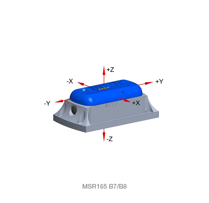
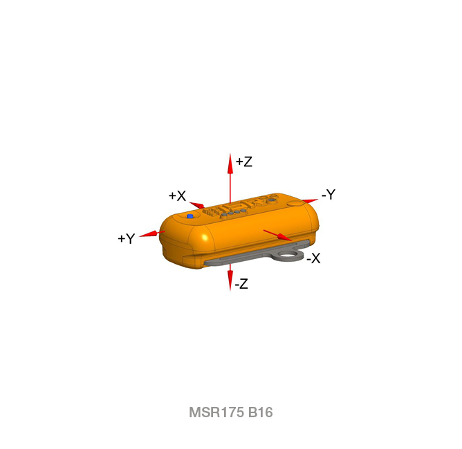
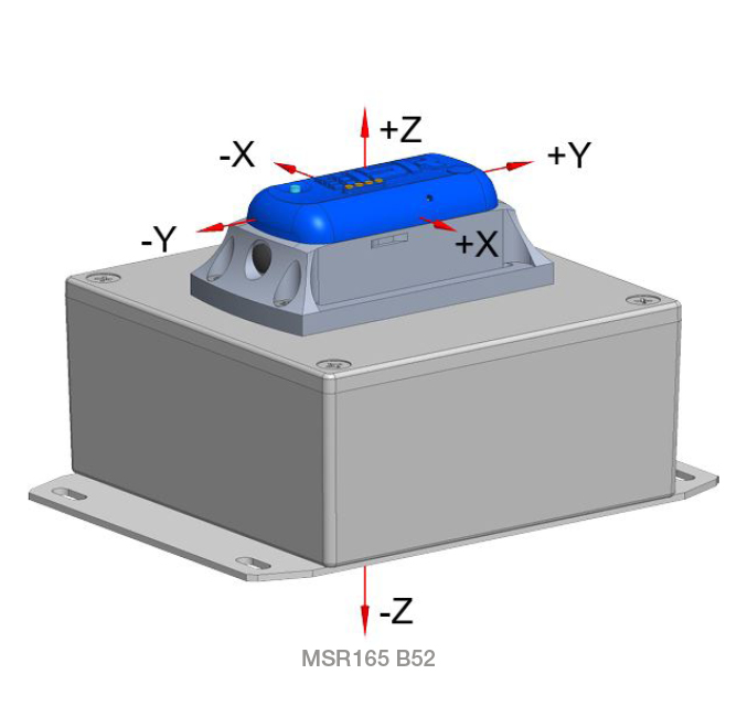
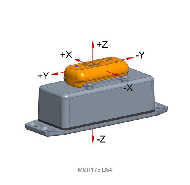
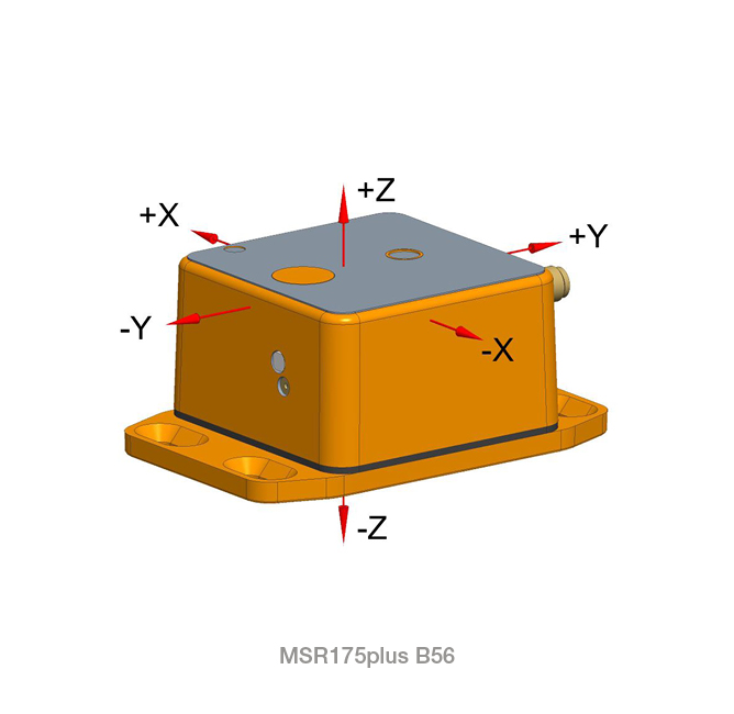
Orientation

Align the axes of the data loggers with the main directions of movement. The data loggers can be mounted in any position. Make a note of the position and direction of the axes for later evaluation.

Determination of the slope

The ±15 sensor additionally measures gravity (direction to the center of the earth ≈ 1g). Due to the static position, the inclination can also be determined.

Example 0…±180°: ACCx = -0.518g, ACCy=0.425g, ACCz=0.741g:

In the setup with «Read» on the MSR145 / MSR165 or «Click here to view values» on the MSR175 and MSR175plus, the current values ACCx, ACCy, ACCz can be read.

Housing types: Outlines, hole patterns, screw connections

Housing types Outlines, Hole patterns Screw connections
MSR165 B7/B8Shock and vibration data logger MSR165, housing type B7 / B8 Umriss/Bohrbild Datenlogger MSR165, Gehäusetyp B7/B8 Thread assembly: e.g. DIN 965A / ISO 7046 A2 M3x8
Tightening torque: 0.45-0.55 NmMounting in wood and sheet metal: e.g. DIN 7983C / ISO 7051 A2 2.9×19
Tightening torque: 0.4-0.5 Nm
MSR175 B16MSR175 transport data logger, housing type B16 Umriss/Bohrbild Datenlogger MSR175, Gehäusetyp B16 Thread assembly: e.g. DIN 7085A / ISO 7045 A2 M6x12 Tightening torque: 4.5-5.0 Nm

Mounting in wood and sheet metal: e.g, DIN 7981C / ISO 7049 A2 5.5×19
Tightening torque: 4.0-4.5 Nm

MSR165 B52


Shock and vibration data logger MSR165, housing type B52

Umriss/Bohrbild Datenlogger MSR165, Gehäusetyp B52 Thread assembly: e.g. DIN 7085A / ISO 7045 A2 M4x10 Tightening torque: 1.2-1.4 Nm

Mounting in wood and sheet metal: e.g. DIN 7981C / ISO 7049 A2 5.5×19
Tightening torque: 1.0-1.2 Nm


MSR175 B54MSR175 transport data logger, housing type B54 Umriss/Bohrbild Datenlogger MSR175, Gehäusetyp B54 Thread assembly: e.g. DIN 7085A / ISO 7045 A2 M4x10 Tightening torque: 1.2-1.4 Nm

Mounting in wood and sheet metal: e.g. DIN 7981C / ISO 7049 A2 5.5×19
Tightening torque: 1.0-1.2 Nm

MSR175plus B56 1)MSR175plus transport data logger, housing type B56
Umriss/Bohrbild Datenlogger MSR175plus, Gehäusetyp B56 Thread assembly: e.g. DIN 965A / ISO 7046 A2 M4x12
Tightening torque: 1.2-1.4 NmMounting in wood and sheet metal: e.g. DIN 7983C / ISO 7051 A2 3.5×19
Tightening torque: 1.0-1.2 Nm

1)  The GPS antenna of data logger MSR175plus, housing type B56 should be attached to the outside of the packaging. The back of the antenna is magnetic. On a non-magnetic body it can be positioned and secured with a wrapping foil.

Mounting instructions for shock and vibration data loggers

MSR165, MSR175, MSR175plus